Crossings on the Port Kelsey
Constructing crossings
Click on image for really big view….
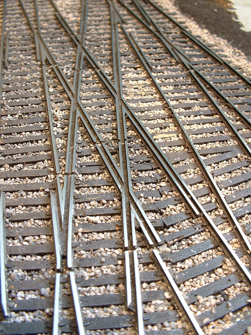
Image Copyright 2005 Tim Warris
I have always felt crossings are the most visually interesting pieces of trackwork on a layout, or the prototype. I make an effort to try and hunt them down when I am rail fanning, but unfortunately, most of the interesting ones have disappeared.
I have 9 so far on my layout, built either by hand or in a fixture at a variety of angles. The ones I built by hand I did by laying two of the rails throughout the entire crossing, and “notching” the other two rails, and placing on top of the first two, creating a lap joint in the rails. I did the same with the guard rails and soldered the flangeways solid. I cleaned out the flangeways with a hacksaw blade, this way I didn’t need to make all the individual pieces of rail and file the various angles. The results were satisfactory.
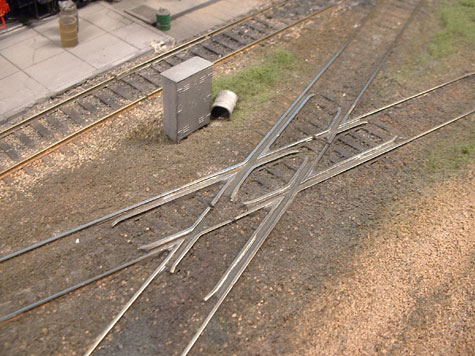
Image Copyright 2005 Tim Warris
The next “phase” of crossings were built in the early versions of my fixture, that I had originally designed just for myself, with no intention of selling them commercially. These were machined of hardwood, with grooves for only the rails. I used the same approach, creating lap joints in the rails and guardrails, and cleaning out the flangeways with a hacksaw blade. Small pieces of scrap rail were soldered to the top of the rails to hold everything in place while I spiked the crossing in place.
The attached picture shows a quad-diamond I built for the industrial switching area of “Gage West” on my Port Kelsey layout. The results are very nice, with all the track and flangeways being in gauger when it was completed, one route is even curved. Ignore the wiring, I had to run it that way because directly below the crossing is a support for the upper deck, I will cover them with ballast later.
Click on image for larger view…
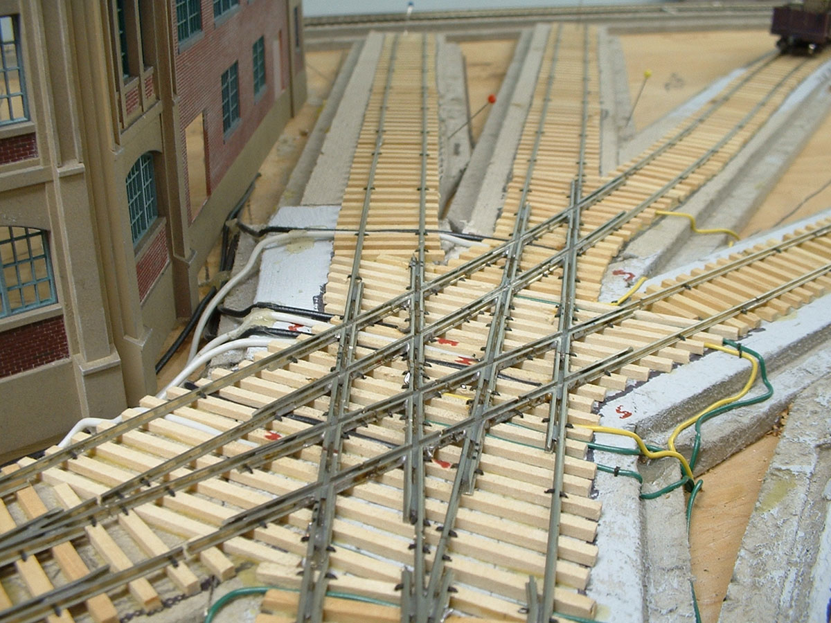
Image copyright 2005 Tim Warris
Now, the crossings I am building I am constructing in the latest generation of assembly fixtures, these are much better in that the rails are all soldered solid to the PC board ties, so the resulting trackwork is very solid and will not move. One of the issues I have with spiking is the slight movement of the rail that sometimes occurs when the spike is driven, and these small, sometimes unnoticeable variations cause “bumps” when trains run through some of the more complex trackwork, and being an incurable perfectionist, these bumps would drive me nuts! This is completely eliminated with the fixture built trackwork as the rails are held precisely in place when soldered. I have attached a picture of a #8 double crossover that I built in a fixture I designed for a customer last year. Again, the results are very nice, with smooth trackwork throughout the entire crossover.
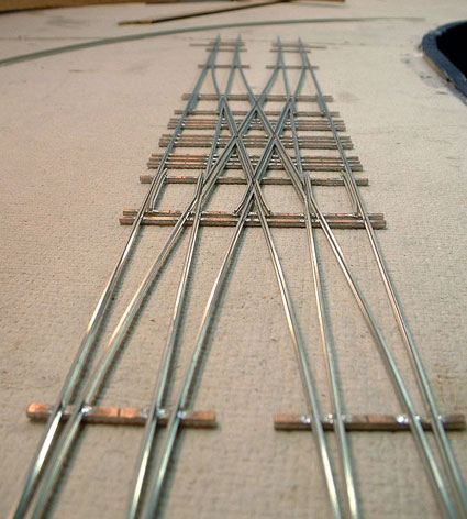
Image copyright 2005 Tim Warris
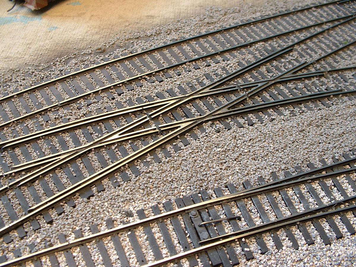
Using the latest version of the fixtures, I now place individual pieces of rail into the fixtures, with the proper angles filed using a Frog Point Grinding Jig. These will hold the rail at the angles needed for the crossing, both the acute and obtuse angles, again, the results are 100% accurate.
Click on image for larger view
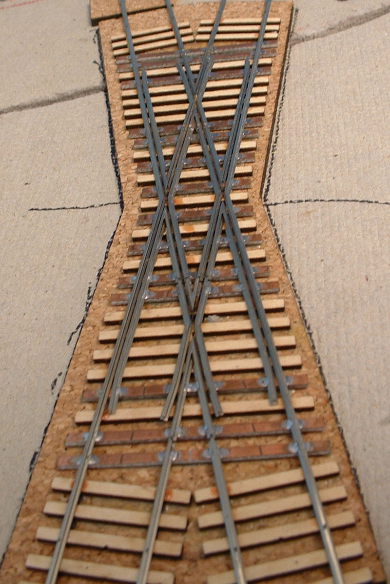
Image copyright 2005 Tim Warris
Being a tool and tie maker I strive to get the most accuracy possible with as little effort and skill necessary (OK, a lazy tool and die maker….)
Click on image for larger view
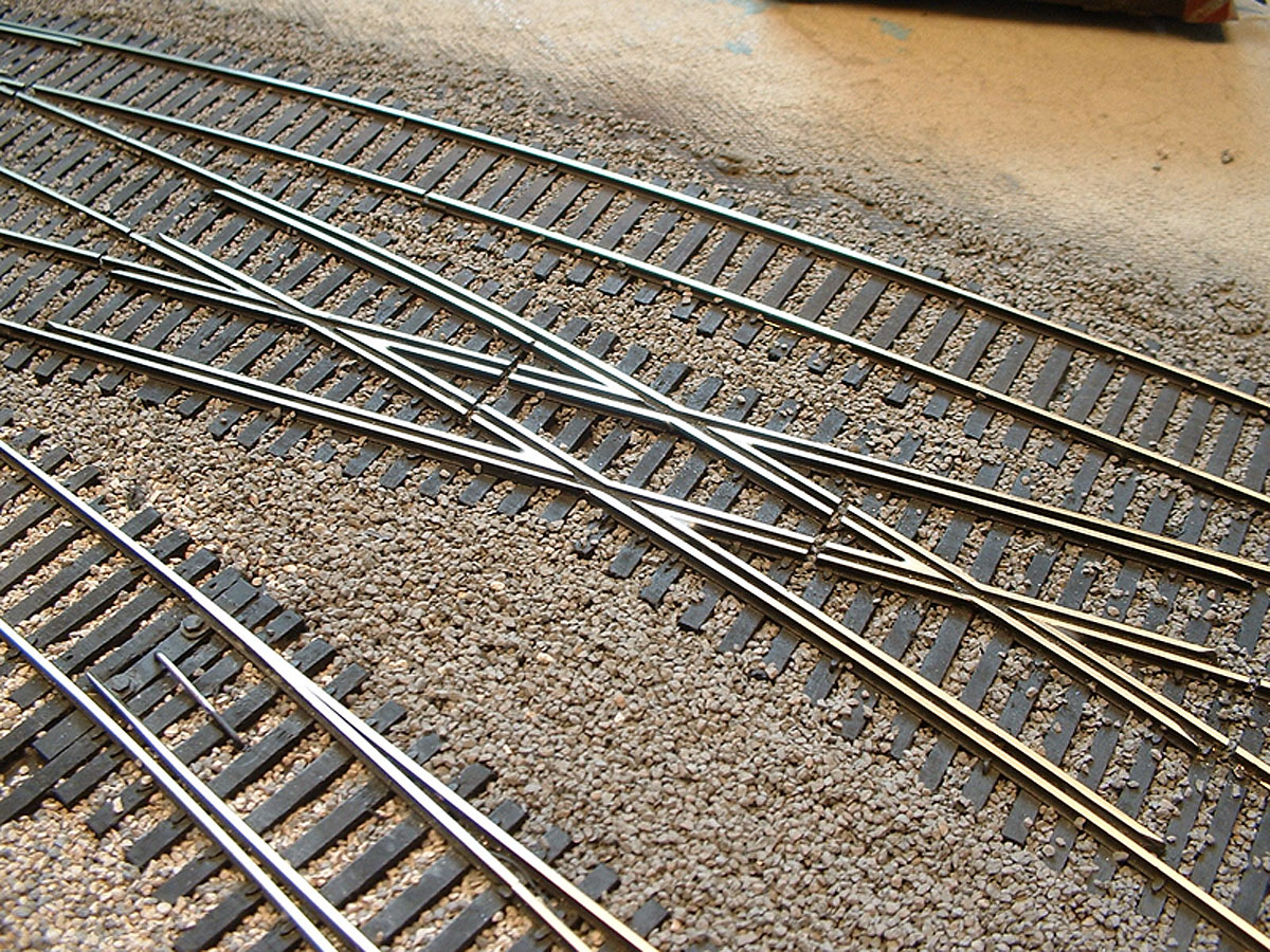
Image copyright 2005 Tim Warris
Click on image for larger view
Thought you might be interested in seeing my approach(s) to building crossings…
Posted by: | 01-17-2005 | 02:01 PM
Posted in: Uncategorized
Wow Tim,
That is some beautiful trackwork. I love the fact that you have some odd angles in the crossings so that you can only deduce that it must be hand laid. Now if I could only keep my guardrails away from my #6 N Scale Turnout stock rails, I’ll be heading in the right direction. Thanks for the inspiration.
Great looking trackwork!
Just one question: why the large gaps, and how do you fill them?
Best regards,
H�vard H,
NORWAY
Thanks for the compliments!
The large gaps that show in the pictures are for the electrical isolation of the frog points in the crossing. When these crossing were built I was using a fairly thick cut-off tool in my Dremel Moto-tool. I now use a much smaller wheel that is much less noticeable.
I should fill the gaps in but have yet not got to that step. The pictures I have on the site are very close shots of the trackwork and seem to make the gaps much more noticeable, when viewed from a normal viewing distance, they can’t really be seen…
Great looking track Tim!
A couple of questions – given that you work with fairly tight tolerances, what are you recommending as roadbed – cork? Other places it looks like homosote. How do accomodate shift and expansion/contraction problems? (I’m handlaying N-scale using PC ties and it turns out roadbed material is critical – I’m not spiking code 40!)
It also looks like you’re filling in the gaps in the foil on the PC-ties – what are you using?
Thanks for the compliment!
The pictures above show a very long timeline in my track laying process. When spiking rails in place I always use Homosote, the ties do not hold much, the roadbed is key to keeping everything in place. Once I switched to using PC board ties, Homosote — and the mess associated with it, was no longer necessary, so I switched to cork that I cut with the laser.
In the 15 years that I have been modeling, I have never had any problems with expansion or contraction of the rail or the roadbed, and in Southern Ontario where the humidy in the summer is only out-done by the dryness in the winter, it is surprising; but I have done nothing extra to prevent it.
None of the gaps are filled in, again, I have never had any problem with them closing up or moving….
My Attempts at Handlaying Turnouts
So far, I’ve made two #6 turnouts. Neither of two I’ve made were ever intended to be used on the layouts, rather I wanted to start making them to see how the process would go.
Dear Tim,
I have found your website, and I am very impressed with the with all your photos of the workshops,and of course the layout of all those points and crossings.
I am interested in building all my own crossings, but would like to know how much it would cost me to set up? As you must relize I
live in the U.K. and wish to know about shipping expenses.
KIND REGARDS.
Eddie.
Dear Tim,
I am getting back into hobby after 4 years of inactivity. A few (likely obvious) questions regarding your beautiful trackwork:
how do you isolate tracks electrically when they are soldered to PC board ties?
what product do I see as the base for your trackwork- is it cork?
when you assemble switches on the workbench with PC board, do you completely avoid track nails, and if so how do you affix to base? Is straight trackwork nailed or glued?
PS- I saw your products at the Lakeshore show for the first time and was quite impressed- once I am tracklaying I will purchase the package.
Very inspiring layout!
I sit in awe–absolutely outstanding trackwork! I’ll be happy to accept your rejects for my layout.
I’m using your trackwork as the gold standard for my first-time flextrack ballasting efforts (I’ll try hand-laying after I cut my teeth on flextrack). What do you use for ballast, and how do you go about ballasting?
Thanks.
Rick Krall
Dear Tim,
your job looks terrific! Congratulations for the spectacular results…
I just have a question concerning the gaps: are they necessary? I remember using the Peco Electrofrog turnouts (on my HO scale diorama) and there seemed to be no need for gaps. These turnouts used to be called “the clever ones” because they were able to feed only a selected way at time.
Their frog was made of metal and there seemed to be no electrical isolation beetwen tracks and frog (unlike the insulfrog ones).
Without gaps, would handlaid tournouts behave in a similar way or would they cause short circuits (as I suppose)?
In a few words, is it necessary to cut small portion of tracks (especially for those close to the frog) or can other alternatives be considered?
Is there a way to make them “clever”?
After examining all the turnouts availbable on the market (from brands such as Shinohara, Roco, Peco, MicroEngineering etc), I am pretty sure I will choose the kits offered by handlaidtrack.com !!
Regards….
Hi Tim – Man, what beautiful track! I’m in the process of determining what three or four Fast Tracks jigs I want to own. Previously I have spiked everything to pine or Homasote. Is there any special preparation needed to use “cork” roadbed with the pc tie method? Do you use the Midwest brand cork roadbed? Also thanks for the links. Great stuff.