I did not want to use the blog for Fast Tracks promotion, but I am really excited about this new tool!
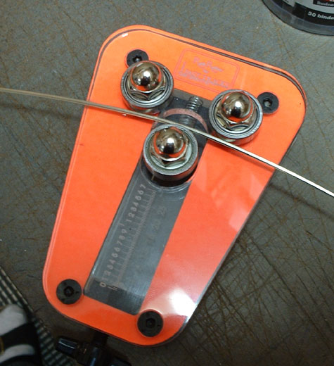
Image copyright 2005 Tim Warris
I asked my brother (Russ) to work on developing a reasonably priced rail bender a while back. He came up with a real winner!
Tonight I decided to work on some of the lower mainline for the lower deck of my Port Kelsey Ry, and required a curved turnout to make it all work. Building a curved turnout needs a lot of curved rail, and the “Rail Roller” he developed works great!
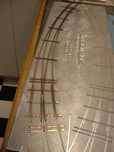
Image copyright 2005 Tim Warris
Or course, Russ made me a custom version….
The polka dots are the logo for my Port Kelsey Railway….
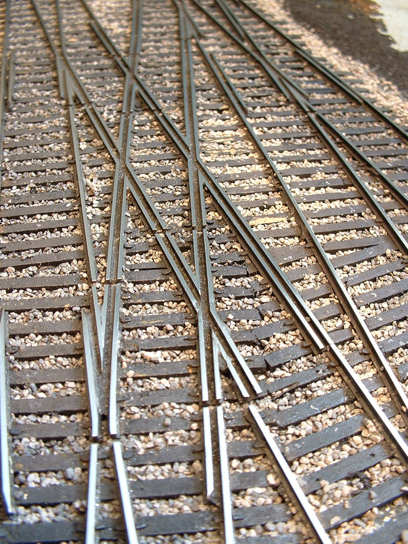
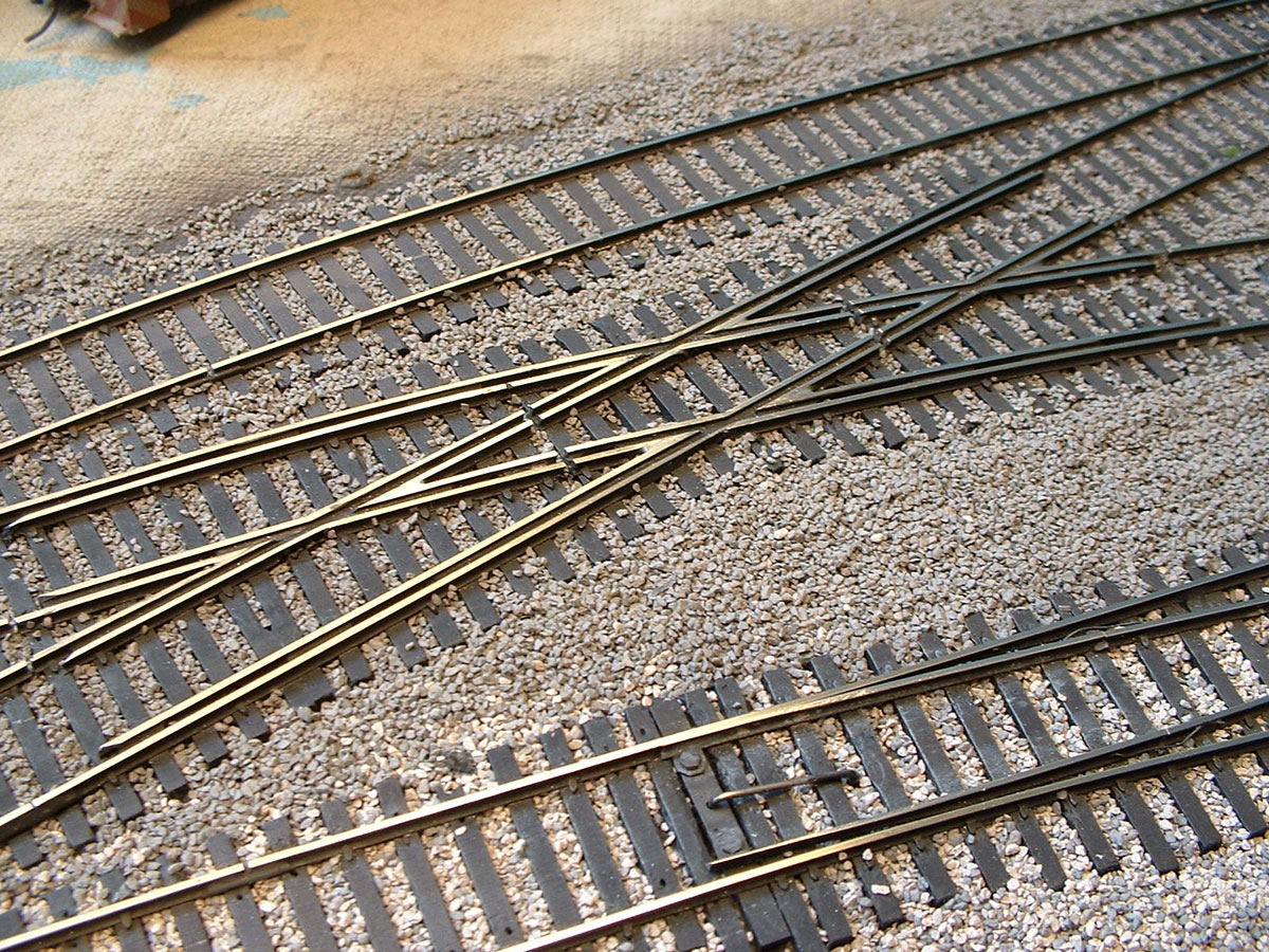
Constructing crossings
Click on image for really big view….

Image Copyright 2005 Tim Warris
I have always felt crossings are the most visually interesting pieces of trackwork on a layout, or the prototype. I make an effort to try and hunt them down when I am rail fanning, but unfortunately, most of the interesting ones have disappeared.
I have 9 so far on my layout, built either by hand or in a fixture at a variety of angles. The ones I built by hand I did by laying two of the rails throughout the entire crossing, and “notching” the other two rails, and placing on top of the first two, creating a lap joint in the rails. I did the same with the guard rails and soldered the flangeways solid. I cleaned out the flangeways with a hacksaw blade, this way I didn’t need to make all the individual pieces of rail and file the various angles. The results were satisfactory.
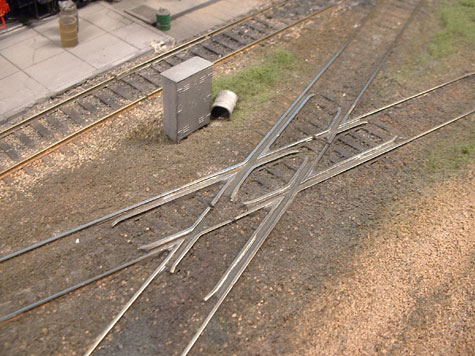
Image Copyright 2005 Tim Warris
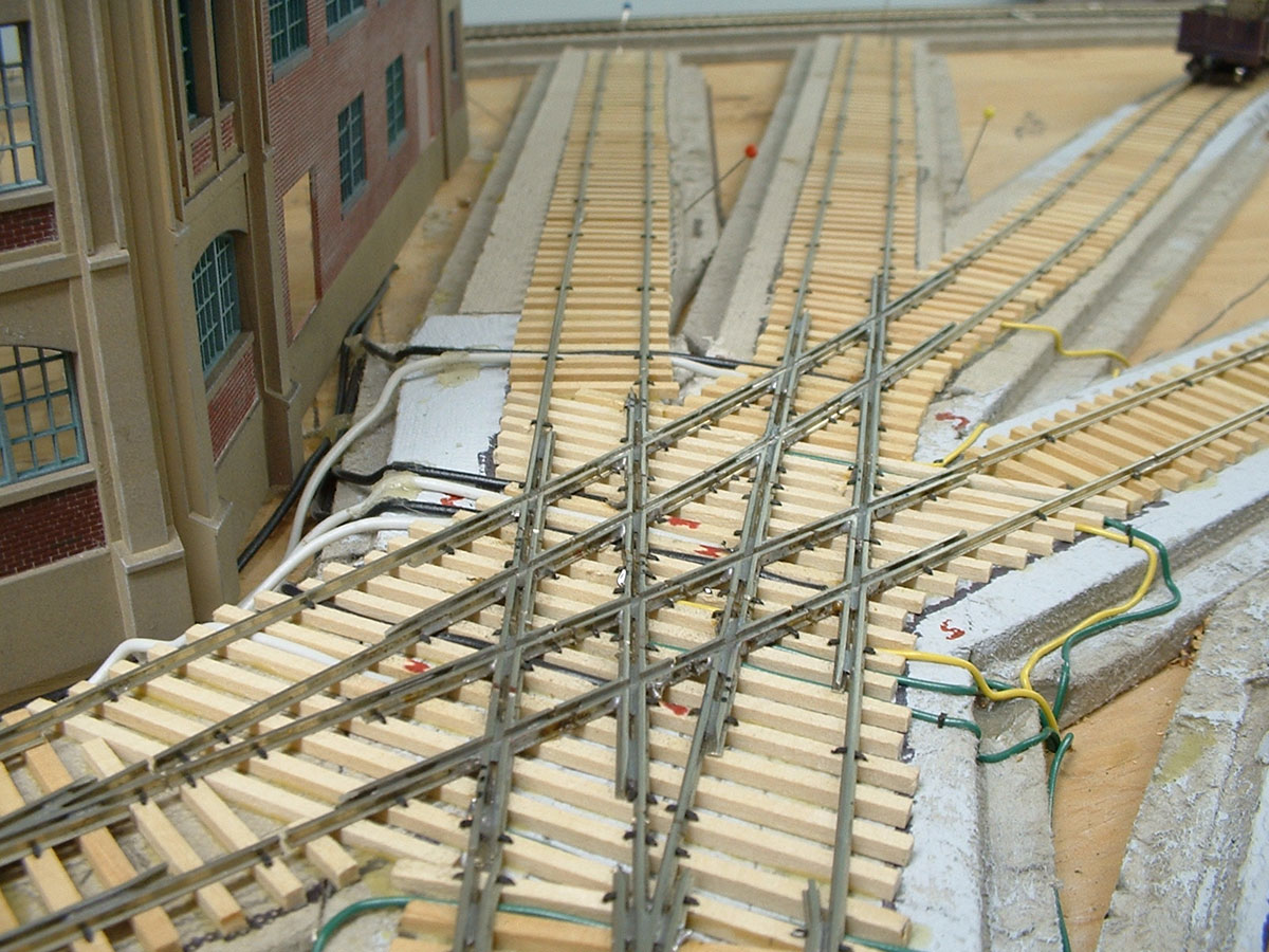
The next “phase” of crossings were built in the early versions of my fixture, that I had originally designed just for myself, with no intention of selling them commercially. These were machined of hardwood, with grooves for only the rails. I used the same approach, creating lap joints in the rails and guardrails, and cleaning out the flangeways with a hacksaw blade. Small pieces of scrap rail were soldered to the top of the rails to hold everything in place while I spiked the crossing in place.
The attached picture shows a quad-diamond I built for the industrial switching area of “Gage West” on my Port Kelsey layout. The results are very nice, with all the track and flangeways being in gauger when it was completed, one route is even curved. Ignore the wiring, I had to run it that way because directly below the crossing is a support for the upper deck, I will cover them with ballast later.
Click on image for larger view…

Image copyright 2005 Tim Warris
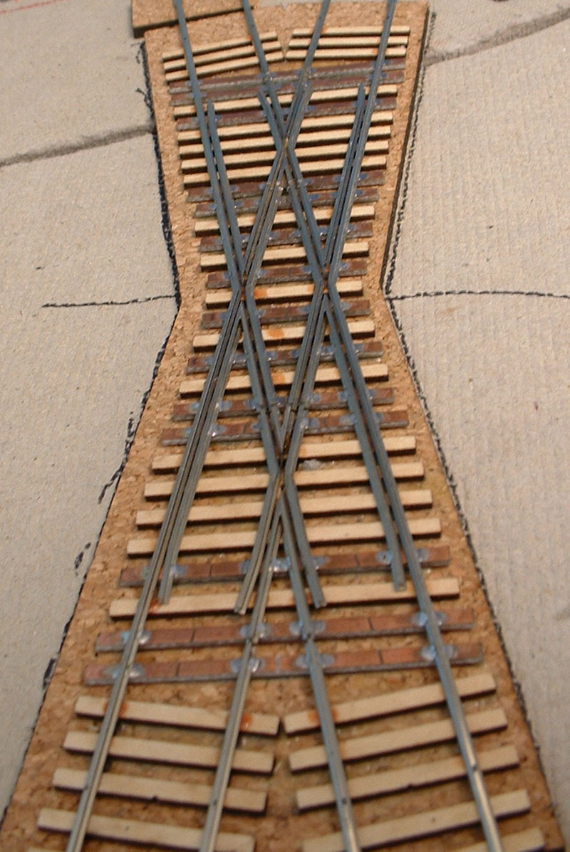
Now, the crossings I am building I am constructing in the latest generation of assembly fixtures, these are much better in that the rails are all soldered solid to the PC board ties, so the resulting trackwork is very solid and will not move. One of the issues I have with spiking is the slight movement of the rail that sometimes occurs when the spike is driven, and these small, sometimes unnoticeable variations cause “bumps” when trains run through some of the more complex trackwork, and being an incurable perfectionist, these bumps would drive me nuts! This is completely eliminated with the fixture built trackwork as the rails are held precisely in place when soldered. I have attached a picture of a #8 double crossover that I built in a fixture I designed for a customer last year. Again, the results are very nice, with smooth trackwork throughout the entire crossover.
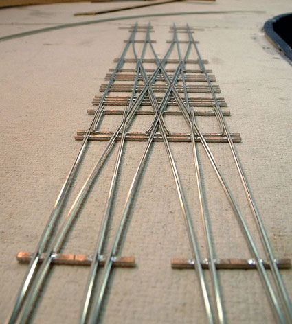
Image copyright 2005 Tim Warris
Using the latest version of the fixtures, I now place individual pieces of rail into the fixtures, with the proper angles filed using a Frog Point Grinding Jig. These will hold the rail at the angles needed for the crossing, both the acute and obtuse angles, again, the results are 100% accurate.
Click on image for larger view
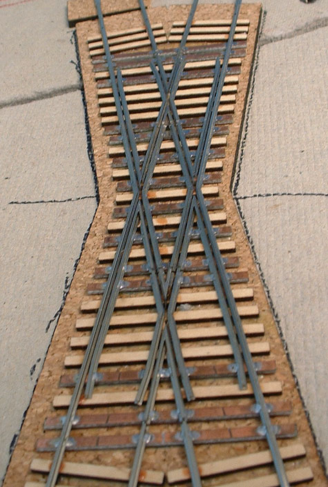
Image copyright 2005 Tim Warris
Being a tool and tie maker I strive to get the most accuracy possible with as little effort and skill necessary (OK, a lazy tool and die maker….)
Click on image for larger view
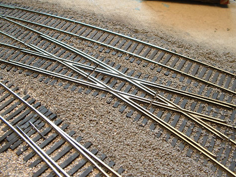
Image copyright 2005 Tim Warris
Click on image for larger view

Thought you might be interested in seeing my approach(s) to building crossings…
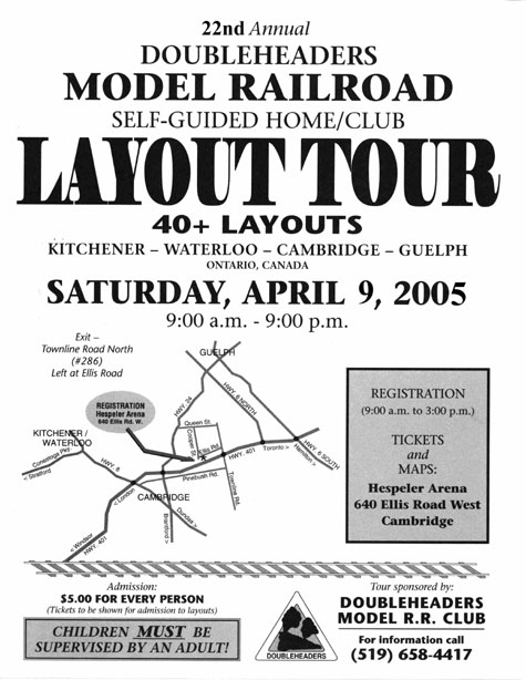
Saturday April 9, 2005
This year is the 22nd annual Doubleheaders Layout Tour, which I have participated in for the last 13 (this year will be 14). The tour is a very well organized event that usually draws 1000 registrants, I usually get around 4-500 visitors that day. Its lots of fun for us, and we have made many friends from the tours that we only see on “Tour Day”. Its turned into quite an annual event here, with most of my (large) family dropping in throughout the day.
The tour is a great motivator, both before the day, and after. I usually cram in a years worth of modeling in the 3 months leading up to the tour, I try to have something new to see every year, this year there is quite a bit new…