Updating turnouts
Trackwork improvements
The layout is becoming a journal of various track laying techniques I have used over the years, from completely laid from scratch, to the original wood fixtures that had no PC ties, to the latest version of the Fast Tracks system.
Copyright Tim Warris 2004
The turnout above was built a few years ago with the first version of a turnout fixture, simply cut into a piece of wood. I would place all the rails into the fixture, fill the frog flange ways with solder, cut the flange way with a piece of a hacksaw blade, solder straps across the tops of the rails and spike the completed turnout in place on the individual wood ties. This was a big step up from how I had been doing it before, which was simply building them in place. The results were OK, but I was constantly frustrated by the spikes moving the rails when pushed in, I just could not get the consistent results I was looking for. There was also a noticeable “bump” when the wheels passed through the frogs.
I had traditionally always used a hinged switch point on my turnouts, not sure why I was so married to this method, but that is how I had always done it. This method required soldering small brass “tabs” onto the bottom of the movable points, drilling a hole in the tab and placing a small 00-90 brass screw through it into a styrene strip to act as a throw bar. This would pivot very freely, but was quite a lot of work to do, at least an extra hour to the construction of a turnout. Inevitably, the styrene would break after a few years and would need to be replaced.
Wanting to improve on the technique, when I installed the turnouts on the upper deck of my layout I decided to try soldering a 00-90 brass screw to the bottom of the points and have a threaded rod screwed into it and fed to the bottom of the layout, and drive it from there. It was even more work, but I figured it would work better. Well, it didn’t, the side torque on the brass screws caused the solder joint to fatigue and break, which they all did.
Retro-fit
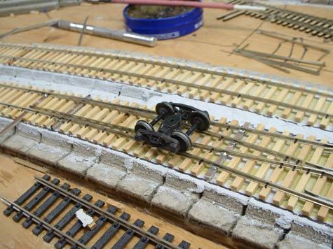
Image copyright Tim Warris 2004
Image copyright Tim Warris 2004
Not wanting to move ahead with a bad design, I decided to re-work all the turnouts on the upper deck by replacing the points using the new method of construction. I pulled out the closure rails to the frog, including the hinged points and faulty throw bar system. Using a PointForm tool I made new lengths of point/closure rails for a solid point turnout. I think back to making points the old way, trial and error, climbing up to the second deck on a ladder each time to check the fit, and usually having to make 4 to get 2 good ones, I sure like this new tool! Once a left and a right were made I spiked them in place (argh!) and soldered on the PC board throw bar. 10 minutes and the job was complete! Compared to the hour it took the first time.
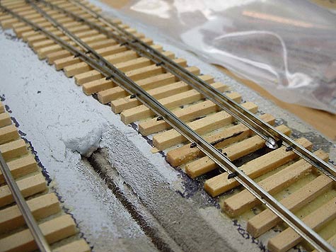
Re-enforcement
One area that always seems to be a source for trouble on a handlaid turnout is where the base of the rail is removed to allow the points to close up tightly to the stock rails. This area can only be spiked on the outside of the rail, and any expansion of the rail will cause this area to warp, making this critical area of a turnout to tight, and will cause derailments that can be hard to diagnose. The fixtures address this problem by placing a PC board tie in this critical area, effectively “welding” the rails in place never allowing them to move. I decided to “dig” out one of the wood ties and replace it with a PC board tie to get the same reliable effect on the older handlaid turnouts. I added on more PC board tie just about the spikes that are acting as a hinge point to allow for good electrical conductivity to the switch points.
Posted by: | 11-10-2004 | 11:11 AM
Posted in: Uncategorized